KTD Engineering Team | Application Engineering & DFM Team | Published: August 13, 2026
Powered conveyor rollers use three drive methods: an internal motor inside the tube, sprocket and chain drive between rollers, and pulley or O-belt drive. They differ in zone control, maintenance access and cost. Only two of the three are fully buildable at component level from your drawing.
Search results for this term are mostly turnkey vendors selling finished conveyor sections by the foot, which is useful if you are buying a line and much less useful if you are building one. Compared with that class of result, this guide stays at the roller: what each drive method demands of the tube, the shaft ends and the drive element, and where the specification usually arrives incomplete.
Powered Conveyor Rollers: Drive Types, Specs & Selection
Three Drive Methods, Stated Plainly
Internal-motor rollers
The motor and gearbox live inside the roller tube. Each driven roller is its own drive unit, typically a low-voltage DC cartridge paired with a zone controller card, with adjacent idler rollers linked by O-belts so one motor turns a short group. This is the architecture behind most zero-pressure accumulation zones built in the last decade.
The consequence people underrate: the drive is now a purchased electromechanical assembly with its own control ecosystem. You are specifying a motor platform as much as a roller.
Sprocket and chain driven rollers
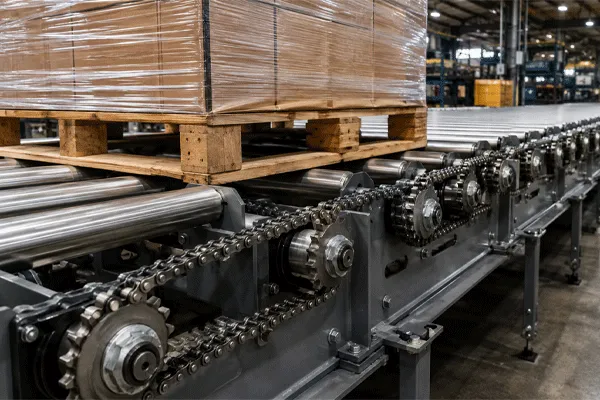
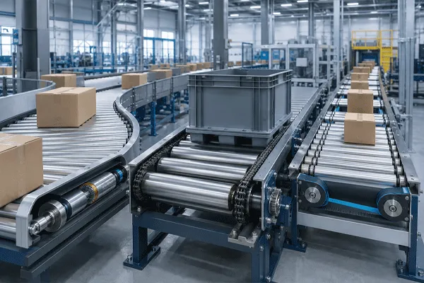
Each roller carries one or more sprockets on the shaft or welded to the tube end, and a chain runs roller to roller. Power comes from a single drive unit at the head, then propagates mechanically down the bed.
This is the method that survives heat, dust, impact and wash-off in ways electronics do not. Chain-driven live roller beds are still the default under foundry loads, tyre handling and heavy pallet transport, and the reason is not nostalgia. There is nothing in the drive path that fails from a voltage transient.
Pulley and O-belt driven rollers
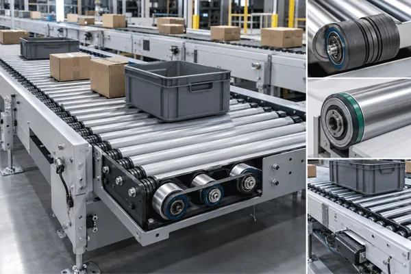
The tube or shaft carries a groove profile, and round belts or a ribbed belt transmit motion between rollers or from a drive shaft below the bed. Quieter than chain, lighter duty, and the belt itself is the designed failure point, which is often the desired behaviour on a line handling cartons that must not be crushed if a roller seizes.
Comparing the Three at Component Level
| Dimension |
Internal-motor roller |
Sprocket / chain driven |
Pulley / O-belt driven |
| Where power originates |
Inside each driven roller |
Single head drive, propagated by chain |
Head drive or line shaft, propagated by belt |
| Zone control and accumulation |
Native, per zone in software |
Requires clutches, brakes or separate drive sections |
Requires separate belt loops or line-shaft spools |
| Typical load class |
Cartons, totes, parcels |
Heavy cases through multi-ton pallets |
Light to medium cartons and totes |
| Noise |
Low |
Highest of the three |
Low |
| Behaviour on jam or seizure |
Motor stalls, controller reacts |
Chain transmits force until something yields |
Belt slips or breaks first |
| Maintenance access |
Roller replaced as a unit |
Chain, sprockets and rollers serviced separately |
Belts replaced individually, quickly |
| Washdown suitability |
Constrained by the motor’s own sealing |
Workable in stainless with sealed bearings |
Workable, belt material dependent |
| Spare-part granularity |
Whole driven roller |
Sprocket, chain link, bearing or tube |
Belt, or pulley groove roller |
| Buildable to your drawing by a component maker |
Tube and end configuration yes, motor cartridge no |
Fully |
Fully |
| Lead-time driver |
Motor platform availability |
Machining and sprocket production |
Machining and pulley production |
Where Buyers Conflate the Terms
“Motorized,” “powered” and “driven” arrive in inquiries as synonyms, and they are not. Powered and driven describe any roller that receives torque. Motorized, in most of the industry’s usage, means the motor is inside that specific tube. An RFQ asking for two hundred motorized rollers when the bed is actually chain-driven will come back with a quotation that is wrong by an order of magnitude, and neither side will understand why for another two emails.
The second confusion runs deeper. Accumulation is treated as a property of internal-motor rollers, as though choosing that drive method buys the behaviour automatically. It does not. Accumulation is a control strategy, and it is achievable on a chain-driven bed with brake-and-clutch zones or on a line-shaft bed with spool slip. The internal-motor architecture makes it cheaper to implement in software rather than making it uniquely possible.
Edge case worth pricing before design freeze: a mixed bed. Lines that transport heavy pallets into a zone where cartons are singulated frequently end up with chain-driven rollers upstream and internal-motor zones downstream, sharing one frame. The interface roller between the two sections sees torque from one method and rotation from another, and it needs a shaft-end and bearing specification that neither standard section drawing covers. Draw that roller separately.
Powered Conveyor Rollers: Drive Types, Specs & Selection
What a Component Supplier Can Actually Build to Drawing
Straight answer, because it saves everyone a week. KTD’s conveyor roller line includes motorized conveyor rollers, sprocket driven conveyor rollers, powered and pulley-driven rollers, gravity rollers, steel rollers and fully custom rollers. For sprocket-driven and pulley-driven configurations, the entire component is manufacturable from your drawing: tube, wall, shaft ends, bearing housing, and the sprocket or pulley that sits on it.
Internal-motor rollers are different in kind. The motor cartridge and its controller are an electromechanical platform, and KTD’s published product data does not state motor voltage, torque or control-protocol specifications. Treat the motor platform as a separate sourcing decision and confirm at inquiry which parts of an internal-motor build fall inside the component scope. A supplier who quotes an MDR platform without publishing its drive data is a supplier you will be reconciling datasheets with later.
That distinction is the practical value of asking a component maker rather than a system vendor. On the two mechanically driven methods, the drive element and the roller come from the same production route, and the fit between them stops being an integration risk.
Roller-Level Specification Fields
| Field |
Published options |
| Tube material |
Carbon steel, 304 or 316 stainless steel, aluminium, PVC |
| Standard tube diameter |
38 mm, 50 mm, 60 mm, 89 mm |
| Length |
Customised to conveyor frame requirements |
| Shaft ends |
Spring-loaded, female-threaded, milled-flat |
| Bearings |
Precision ball bearings, stamped bearings, polymer bearing housings |
| Load range served |
Lightweight parcel conveyors through heavy-duty systems handling multi-ton pallets |
| Tolerance capability |
To H6 |
| Custom order quantity |
From 20 pieces, scaling to 10,000+ per production run |
| Accepted drawing formats |
STEP, IGES, DWG, DXF, SLDPRT, PDF |
| Production route |
DFM review, prototype, First Article Inspection, mass production, CMM and material inspection |
Shaft-end choice tracks the drive method more tightly than most drawings acknowledge. Spring-loaded ends drop into a frame fast and suit gravity and light powered sections where the roller does not resist torque. Female-threaded ends give a bolted, repeatable location that survives removal cycles. Milled-flat ends resist rotation, which is what a shaft carrying a sprocket under load actually needs. Specifying a spring-loaded shaft on a chain-driven roller is a design error that passes drawing review regularly.
Annual production capacity across KTD’s component range is stated at 100,000+ units, which matters here mainly because a conveyor bed is not a single-part purchase. A 40-metre driven section is several hundred rollers with matched drive elements, and consistency across that quantity is a different problem from making one good roller.
The Drive Interface Is Where Drawings Go Incomplete
Roller dimensions get specified carefully. The thing that transmits torque into the roller often gets one line and a part number from a previous project.
On the sprocket side.
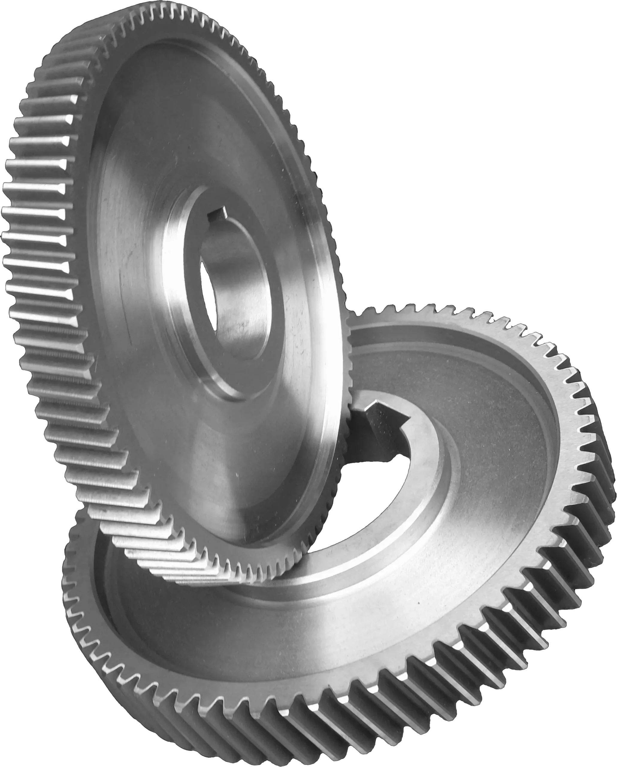
KTD produces chain sprockets across roughly 1/4 inch to 2 inch ANSI pitch plus metric equivalents, in simplex, duplex, triplex and custom multi-strand configurations, in 1045 carbon steel, alloy steel and 304/316 stainless. Bore options cover pilot bore, finished bore with keyway or set screw, and taper-bushed configurations. The applicable standards referenced are ASME B29.1-2011 (R2022), published by ASME and available through ANSI, together with ISO 606 from the International Organization for Standardization, which covers dimensions, tolerances and strength for short-pitch precision roller chains and their associated sprockets, and DIN 8187.
For chain-through roller beds, the double-strand configuration matters: one strand receives from the previous roller, one delivers to the next. Whether that is achieved with duplex sprockets or two simplex sprockets on a longer shaft extension changes the shaft-end drawing, and it is worth deciding before the frame width is fixed.
On the pulley side.
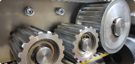
Poly-V profiles PH, PJ, PK, PL and PM at 40° groove angle are produced in HT150/HT200 grey cast iron, 6061-T6 aluminium and carbon steel, to ISO 9982 and DIN 7867. Where the application needs actual synchronisation rather than friction drive, timing pulleys and belts cover HTD 3M through 14M, imperial MXL through XXH, and T2.5 through T20 profiles, with polyurethane and rubber belt constructions available.
The sourcing point is straightforward: when the roller and its sprocket or pulley are made on the same production route, the tolerance stack between them stops being an assumption you carry into assembly.
Powered Conveyor Rollers: Drive Types, Specs & Selection
Eight Questions Before You Fix the Drive Method
- What is the heaviest single unit load, and what is the pitch under it?Load per roller drives tube diameter and wall before anything else does.
- Does the line need accumulation, and does it need to be zero-pressure?If yes, cost the control strategy, not just the rollers.
- What is the environment?Wash-down chemistry, ambient temperature, abrasive dust and impact each eliminate a drive method faster than budget does.
- What is the acceptable failure mode?Decide whether a jam should stall a motor, snap a belt or transmit force through a chain, then choose the method that produces that behaviour.
- Who maintains it, and with what spares?Internal-motor beds are replaced at roller granularity. Chain beds are repaired at link and sprocket granularity. That decision outlives the purchase order.
- What is the control architecture you already run?Adding a second motor platform with its own protocol into a plant standardised on something else is a support cost that never appears in the roller quotation.
- What is the noise limit in that space?Chain drive is loud, and in enclosed pick zones this is a genuine constraint rather than a comfort preference.
- Which parts do you want single-sourced?If the answer includes the drive element, that favours the mechanically driven methods.
Work through these before the frame drawing is released, because items 1, 3 and 8 change the roller drawing and items 2 and 6 change the panel.
The Trade-offs, Specifically
Internal-motor rollers concentrate cost and risk in the drive unit. Per-zone control and quiet running are real gains. The exposure is that a failed roller is a failed motor, replaced as an assembly, and the platform’s availability governs your spares position for the life of the line. If that platform is discontinued in eight years, the bed is a retrofit project.
Chain drive buys durability and spends noise, guarding and lubrication. It is the method that keeps running under conditions that damage electronics. It also needs chain guards, periodic tensioning, lubrication management in areas where lubricant contamination is a concern, and it will not be quiet.
Pulley and O-belt drive is the light-duty compromise, and the limit is torque. Belts run quietly and replace in seconds, and the slip behaviour protects product. Once the load per roller climbs, the same slip that protected the carton becomes an inability to move the pallet.
All three are constrained by deflection over span, and none of the drive brochures mention it. A wide bed with a heavy centred load deflects the tube, and deflection loads the bearings off-axis regardless of what turns the roller. Confirm span, pitch and wall thickness together during DFM review rather than reading capacity off a diameter.
Quality Documentation and Pricing
KTD states that its quality management system is certified to ISO 9001:2015. The International Organization for Standardization identifies ISO 9001 as the internationally recognised quality management system standard, which speaks to process control and traceability rather than to any specific roller’s performance. Request the certificate at supplier qualification and read its stated scope.
Pricing is project-specific and provided upon quotation based on material, dimensions, machining complexity, quantity, surface treatment and other technical requirements.
For a driven bed, the variables that move the number most are tube material and diameter, the drive element specification, bearing class, and total quantity. Custom orders start from 20 pieces, so a pilot section can be built and run before the full bed is committed.
FAQ
Q: Is a motorized roller the same thing as a powered roller?
A: No. Powered and driven describe any roller receiving torque, by any method. Motorized generally means the motor sits inside that specific roller tube. Sprocket-driven and belt-driven rollers are powered but not motorized, and quoting one against the other produces very different numbers.
Q: Can I get accumulation without internal-motor rollers?
A: Yes. Accumulation is a control strategy rather than a property of one drive type, and it is implemented on chain-driven beds using brake and clutch zones and on line-shaft beds using spool slip. Internal-motor architecture makes zero-pressure accumulation cheaper to implement in software, which is a different claim from making it exclusive.
Q: Which drive method suits washdown food lines?
A: Mechanically driven configurations in 304 or 316 stainless with sealed bearing housings are the straightforward route, because the sealing problem is confined to the bearing. Internal-motor rollers in wet zones depend on the motor platform’s own sealing rating, which needs to be assessed against the actual cleaning procedure rather than assumed.
Q: Can KTD supply the sprockets and pulleys with the rollers?
A: Yes. Chain sprockets across ANSI and metric pitch ranges and Poly-V and timing pulleys are produced in-house alongside the conveyor roller line, so the roller and its drive element can come from one production route.
Q: What information does a roller quotation actually need?
A: Unit load and roller pitch, between-frame dimension and face length, drive method with the drive element specification, tube material, bearing preference and required shaft end, plus quantity. A drawing in STEP, IGES, DWG, DXF, SLDPRT or PDF covers most of it in one exchange.
Q: What is the smallest quantity worth quoting?
A: Custom orders start from 20 pieces, which is generally enough for a pilot section or a first-article evaluation before committing a full bed.












 17:49
17:49