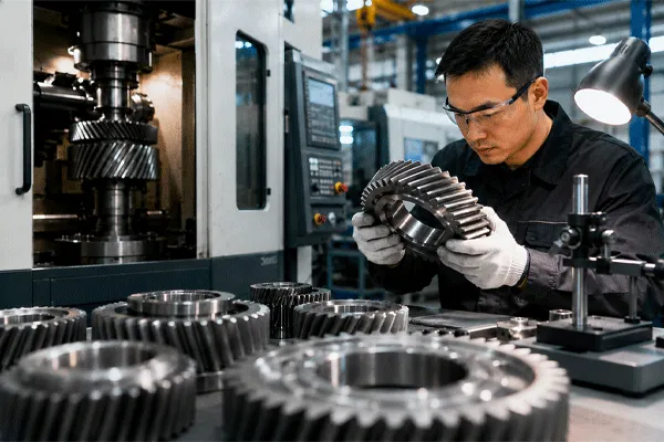
A noisy or overloaded gear drive can create vibration, heat, wear, and costly downtime. These problems grow worse at higher speeds. A correctly designed helical gear provides smoother tooth engagement, better load sharing, and quieter power transmission than many basic straight-tooth designs.
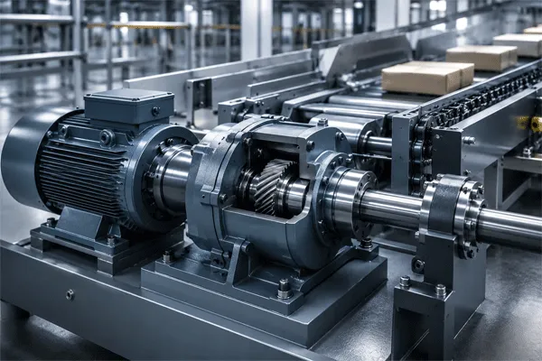
A engrenage hélicoïdal is used to transfer motion and power between rotating shafts in gearboxes, vehicles, pumps, compressors, conveyors, machine tools, lifting equipment, and industrial machinery. Its angled teeth engage gradually, allowing smoother, quieter operation and greater load capacity than a comparable spur gear, although it also creates axial thrust.
À quoi sert un engrenage hélicoïdal dans la transmission de puissance ?
Schéma de l'article
- What is a helical gear?
- How does a helical gear transmit power?
- What is the advantage of helical gear teeth?
- What are the main types of helical gears?
- How does a helical gear compare with a spur gear?
- What role does the helix angle play?
- Where are helical gears commonly used?
- What are the disadvantages of helical gears?
- How are helical gears manufactured?
- How should engineers select a helical gear set?
- Why do lubrication and bearing design matter?
- Foire aux questions
- Points clés à retenir
What Is a Helical Gear?
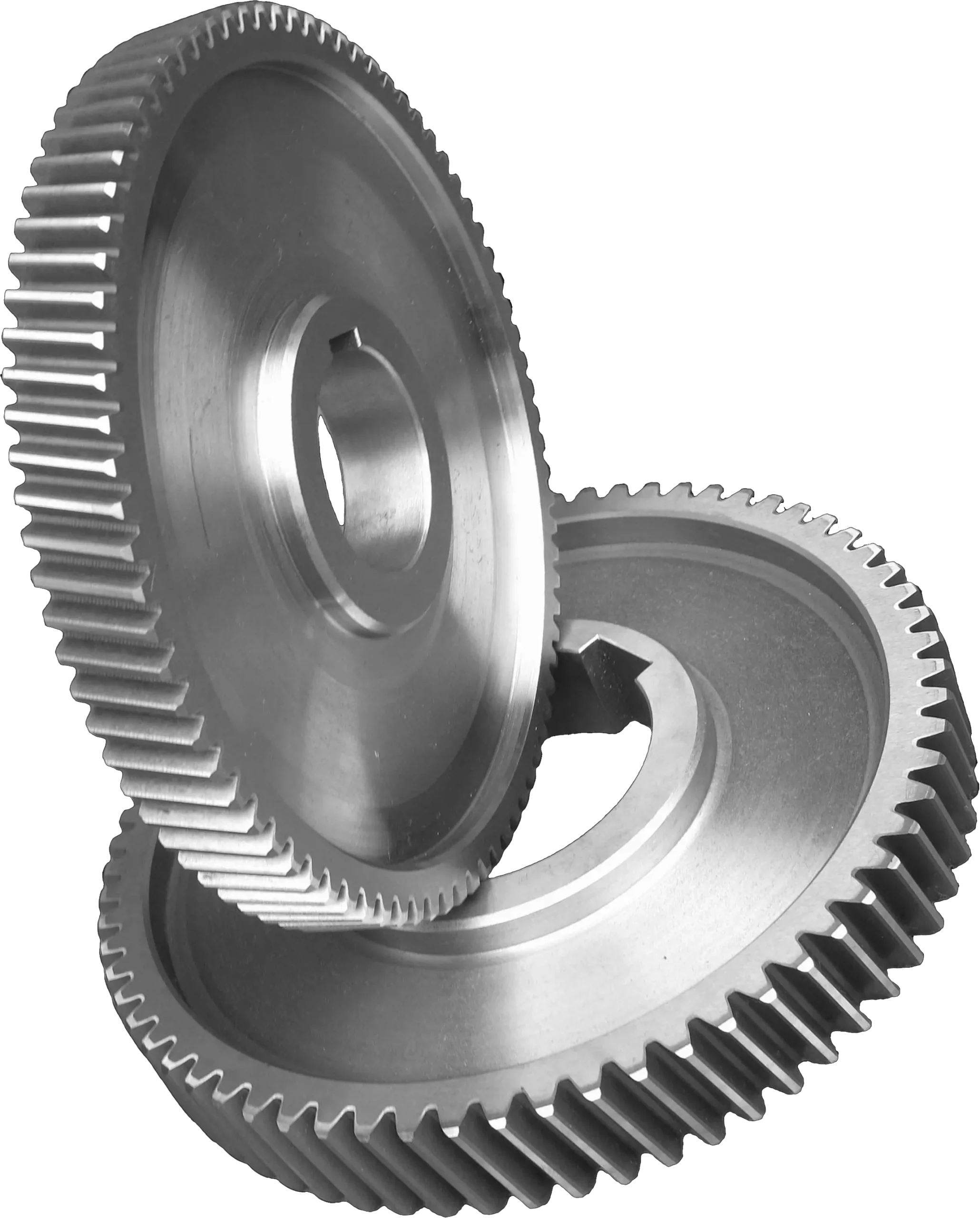
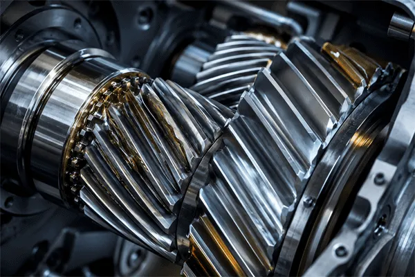
A helical gear is a cylindrical gear with teeth cut at an angle to the axis of the gear. The teeth do not run straight across the gear face. Instead, they follow a slanted path around the gear.
This angled tooth arrangement separates the helical gear from a spur gear. The teeth of a spur gear run parallel to the shaft. They usually meet across the full tooth width at nearly the same moment. Helical teeth engage more gradually.
A helical gear is a type of gear commonly used on parallel shafts. It can also be used in certain crossed-axis arrangements, although a crossed helical gear has different load and efficiency limits from a parallel-shaft gear set.
The main parts and design terms include:
- Gear teeth
- Diamètre primitif
- Module or diametral pitch
- Helix angle
- Angle de pression
- Gear face width
- Tooth hand
- Bore and hub
- Rapport de transmission
- Entraxe
- Réaction
KHK describes helical gears as cylindrical gears with slanted tooth traces. Compared with spur gears, they have greater tooth overlap, smoother engagement, less vibration, and quieter operation.
How Does a Helical Gear Transmit Power?
A pair of helical gears transfers torque when the teeth of the driving gear push against the mating gear teeth. The driven gear then rotates in the opposite direction for an external gear mesh.
The main difference is how contact begins. A spur gear tooth often makes contact across much of its width at once. A helical gear tooth starts contact near one end and gradually brings more of the tooth face into the mesh.
This progressive engagement creates a smoother transmission of force:
Spur Gear Contact:
Full-width engagement → faster load application

Helical Gear Contact:
Edge engagement → gradual overlap → full contact → gradual exit
More than one pair of teeth may share the load during part of the rotation. This higher contact ratio than spur gears can improve smoothness and support greater transmitted load when the complete gear design, materials, bearings, lubrication, and alignment are correct.
A pair of helical gears for parallel shafts normally uses the same helix angle but opposite tooth hands. A right-hand helical gear mates with a suitable left-hand gear. The module, pressure angle, center distance, tooth geometry, and other design conditions must also match.
What Is the Main Advantage of Helical Gear Teeth?
The main advantage of helical gear teeth is gradual engagement. This reduces sudden impact as the mating teeth enter the gear mesh.
The practical advantages of helical gears can include:
- Quieter gear operation
- Lower vibration
- Smoother rotation
- Higher tooth contact ratio
- Better load distribution
- Good performance at higher speed
- High power transmission capacity
- More stable motion in precision equipment
These characteristics explain why helical gears are preferred in enclosed gearboxes, automotive transmissions, industrial speed reducers, compressors, and other systems that must run smoothly.
A well-designed helical gear can also support a wide gear face. As contact moves across the face, several tooth sections help carry the load. This allows efficient power transmission in compact gear assemblies.
However, the advantages do not come from the tooth shape alone. Gear quality, alignment, shaft stiffness, housing rigidity, bearings, lubrication, heat treatment, and surface finish all affect the final performance.
A strong tooth design cannot correct a weak shaft, poor bearing support, or misaligned housing.
À quoi sert un engrenage hélicoïdal dans la transmission de puissance ?
What Are the Main Types of Helical Gears?
Several helical gear types are used in mechanical systems. Engineers select among them based on shaft position, torque, speed, space, axial thrust, and manufacturing requirements.
Single Helical Gears
Single helical gears have one continuous set of angled teeth. They are common in parallel-shaft industrial gearboxes and vehicle transmission systems.
Their design is relatively compact, but the angled tooth load produces an axial force along the shaft. Bearings and shoulders must control this thrust.
Double Helical Gears
A double helical gear has two sets of gear teeth with opposite helix directions on the same gear body. The opposing tooth directions can balance much of the axial force.
The two sides may have a central relief groove that separates them. This groove provides space for the cutting tool during some gear manufacturing processes.
Double helical designs are used for high-load industrial applications such as large compressors, marine drives, heavy rolling equipment, and high-power speed reducers.
Herringbone Gears
A herringbone gear is similar to a double helical gear, but its opposing teeth often meet in a V-shaped pattern without a central gap.
A herringbone gear can provide smooth, high-capacity transmission while reducing net axial thrust. It is more difficult and costly to manufacture than many standard helical gears.
Crossed Helical Gears
Crossed helical gears transmit motion between non-parallel, non-intersecting shafts. This arrangement is also called a screw gear system in some technical references.
Unlike a parallel pair of helical gears, crossed helical gears have significant sliding contact. Their load-carrying capacity is usually lower, making them more suitable for light-duty motion transmission than large power transmission. KHK notes that screw or crossed helical arrangements have point contact and require careful lubrication.
Helical Rack and Pinion
A helical pinion can mesh with a helical rack to convert rotary motion into linear movement. This arrangement may provide smoother travel than a straight rack and spur gear system.
What Is the Difference Between a Spur Gear and Helical Gear?
A spur gear and helical gear can both transmit power between parallel shafts. The key difference is tooth direction.
Spur gear teeth are straight and parallel to the gear axis. A helical gear has teeth cut at an angle to the axis.
Spur and Helical Gear Comparison
| Fonctionnalité |
Engrenage droit |
Engrenage hélicoïdal |
| Orientation des dents |
Hétéro |
En biais |
| Engagement des dents |
More sudden |
Gradual |
| Noise at high speed |
Usually higher |
Généralement inférieur |
| Vibration |
More noticeable |
Smoother |
| Poussée axiale |
Little or none from tooth angle |
Présent |
| Manufacturing |
Simpler |
Plus complexe |
| Bearing requirement |
Mainly radial loading |
Radial and axial loading |
| Contact ratio |
Generally lower |
Generally higher |
| Typical cost |
Inférieur |
Plus élevé |
| High-speed use |
Limited by noise and impact |
Often preferred |
| Efficiency |
Élevé |
High, with some added sliding loss |
| Common applications |
Simple drives and low-speed machinery |
Gearboxes, vehicles, compressors, industrial drives |
Spur gears are simple, economical, and efficient. They remain an excellent choice for many low- and moderate-speed gear applications.
Compared to spur gears, a helical gear normally provides smoother operation but places more complex loads on the shaft and bearings. The best type of gear depends on the whole machine.
The difference is not simply “basic versus advanced.” A properly designed spur gear can outperform a poorly selected helical gear.
How Does the Helix Angle Affect Helical Gear Design?
The helix angle is the angle between the tooth direction and the gear axis. It has a major effect on tooth engagement, axial thrust, contact ratio, and manufacturing geometry.
As the helix angle increases, tooth overlap can also increase. This may produce smoother contact and allow more teeth to share the load.
But a larger angle also increases axial force. The bearings, shaft shoulders, housing, and lubrication system must manage that extra thrust.
A simplified relationship looks like this:
Larger Helix Angle
        │
        ├── More gradual tooth overlap
        ├── Potentially smoother operation
        ├── Greater axial thrust
        ├── More sliding contact
        └── More demanding bearing design
The helix angle of both gears must be compatible. For an external pair on parallel shafts, the gears normally have equal angles but opposite hands.
The pressure angle is also important. It affects tooth shape, separating force, tooth strength, and compatibility with the mating gear.
ISO 6336 provides internationally recognized methods for evaluating the load capacity of cylindrical spur and helical involute gears. The standard covers factors related to tooth-root breakage, pitting, scuffing, micropitting, and other design risks within its defined scope.
A qualified designer should therefore evaluate more than diameter and tooth count. The complete calculation may include:
- Puissance d'entrée
- Input and output speed
- Required gear ratio
- Service factor
- Choc de charge
- Cycle de service
- Tooth bending strength
- Surface contact stress
- Déformation de l'arbre
- Bearing life
- Lubrification
- Heat generation
- Housing stiffness
- Manufacturing quality
- Durée de vie prévue
What Is a Helical Gear Used For?
A engrenage hélicoïdal is used where a machine needs reliable torque transmission with lower noise, reduced vibration, or higher load capacity than a basic straight-tooth arrangement can provide.
Automotive and Vehicle Transmissions
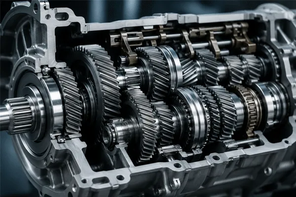
Helical gears are commonly used in manual gearboxes, automatic transmission assemblies, differentials, transfer systems, and auxiliary vehicle drives.
Their gradual tooth engagement helps reduce noise and vibration at vehicle operating speeds. Reverse gears in some older or simpler transmission designs may use spur teeth, which helps explain their more noticeable sound.
Industrial Gearboxes
Industrial speed reducers often use helical gear sets to lower motor speed and increase output torque.
Applications include:
- Systèmes de convoyage
- Concasseurs
- Mixers
- Pompes
- Fans
- Agitators
- Machines d'emballage
- Lignes de production
- Material-handling equipment
Machine Tools
CNC machines, lathes, milling machines, grinding equipment, and other production systems use precision gear components where stable speed and controlled motion are important.
A precision gear set must control tooth profile, pitch accuracy, helix accuracy, backlash, runout, and surface condition.
Compressors and Pumps
Compressors, blowers, and industrial pumps may use a helical gear drive to transmit high power while limiting noise and vibration.
The exact gear selection depends on speed, torque, lubricant, operating temperature, and continuous-duty requirements.
Elevators and Lifting Equipment
Helical gear reducers may be used in lifting machinery, cranes, hoists, and elevator drive systems. These applications require careful safety factors, braking integration, bearing selection, and housing design.
Marine and Heavy Industrial Systems
Double helical or herringbone designs may be selected for large marine and industrial drives where high torque and balanced thrust are important.
Printing and Packaging Machinery
Smooth motion helps reduce vibration in printing, converting, bottling, labeling, and packaging lines. Gear accuracy matters because speed variation can affect registration and product quality.
Renewable Energy and Power Equipment
Helical gear stages may be found in wind turbine gearboxes and other energy systems. These applications require detailed fatigue, lubrication, temperature, and service-life analysis.
À quoi sert un engrenage hélicoïdal dans la transmission de puissance ?
Are Helical Gears Used in Semi Trailers?
A standard semi-trailer axle does not normally use a powered transmission like a truck drive axle. However, gear-driven systems may appear in selected trailer equipment and related heavy-duty machinery.
Depending on the trailer design, geared mechanisms may be used in:
- Landing-gear drive assemblies
- Mechanical lifting devices
- Winches
- Cable systems
- Hydraulic pump drives
- Tanker pumping equipment
- Moving-floor systems
- Matériel à chargement automatique
- Removable gooseneck operating systems
- Workshop and trailer-production machinery
Not every one of these mechanisms uses a helical gear. Some designs use a spur gear, worm gear, bevel gears, chain drive, hydraulic cylinder, or planetary gear set.
As a professional semi-trailer manufacturer, we evaluate the complete operating system rather than selecting components by name alone. Load, road conditions, maintenance access, expected cycle frequency, corrosion exposure, and local parts availability all influence the final design.
For fleet owners, the useful question is not only, “Does this trailer use a helical gear?” It is also:
- Can the mechanism handle the working load?
- Is the system easy to lubricate?
- Are bearings properly supported?
- Can local technicians service it?
- Are spare parts available?
- Is the operating method safe?
- Has the complete assembly been tested?
What Are the Disadvantages of Helical Gears?
The disadvantages of helical gears should be considered before selecting them.
Axial Thrust
The most important limitation is axial force. Because the teeth are angled, helical gears produce axial thrust along the gear shaft.
Bearings must carry both radial and axial loads. Incorrect bearing selection can cause heat, noise, shaft movement, uneven gear contact, and early failure. KHK specifically warns that bearings used with helical gears must be selected to handle the resulting thrust force.
More Complex Manufacturing
Helical gears are manufactured with tighter control over helix geometry, tooth profile, pitch, lead, and surface finish. Production may require specialized cutting, grinding, inspection, and tooling.
Higher Cost
The gear itself, bearings, shafts, housing, and assembly process may cost more than an equivalent simple spur gear drive.
Sliding Friction and Heat
The angled teeth create some sliding action across the gear face. This can increase friction and heat compared with idealized straight-tooth rolling contact.
Good lubrication becomes essential.
Sensitivity to Alignment
A helical gear set can develop poor contact if shafts are misaligned or the housing deflects under load. Edge loading can lead to pitting, wear, heat, and tooth damage.
More Difficult Maintenance
A worn helical gear should normally be evaluated with its mating gear. Replacing only one component may create poor mating gear contact when the remaining gear is already worn.
How Are Helical Gears Manufactured?
Gear manufacturing begins with material selection and a defined engineering drawing. Common gear materials include alloy steel, carbon steel, stainless steel, cast iron, bronze, engineering polymers, and other application-specific materials.
A typical gear production route may include:
- Material preparation
- Forging, casting, or bar cutting
- Turning the blank
- Bore and hub machining
- Gear hobbing or shaping
- Traitement thermique
- Tooth grinding or finishing
- Deburring and cleaning
- Dimensional inspection
- Gear tooth inspection
- Surface treatment
- Final assembly testing
Gear hobbing is a common method used to cut helical teeth. A gear hobbing machine coordinates the rotation of the gear blank and cutting tool to create the required tooth form and helix.
KHK explains that certain helical gears can be cut with the same hob used for spur gears when the normal module and relevant pressure angle remain compatible, although tool positioning must follow the required helix.
Higher-quality requirements may add:
- CNC gear grinding
- Profile modification
- Lead crowning
- Shot peening
- Case carburizing
- Trempe par induction
- Nitruration
- Magnetic-particle inspection
- Coordinate measurement
- Single-flank or double-flank testing
- Noise and vibration testing
A trusted gear manufacturer should confirm the material, heat treatment, gear accuracy grade, tooth hardness, inspection method, allowable torque, lubrication, and mating conditions.
How Should Engineers Select a Helical Gear Set?
Selecting a helical gear set begins with application data. A catalog diameter and tooth count are not enough.
Engineers should define:
| Design Input |
Pourquoi c'est important |
| Puissance d'entrée |
Determines transmitted load |
| Vitesse d'entrée |
Affects pitch-line velocity and heat |
| Output speed |
Establishes the required reduction |
| Rapport de transmission |
Defines speed and torque relationship |
| Cycle de service |
Separates occasional from continuous use |
| Charge de choc |
Affects service factor |
| Disposition des arbres |
Determines gear type |
| Espace disponible |
Limits diameter and face width |
| Noise target |
Influences tooth form and accuracy |
| Lubrification |
Controls wear and temperature |
| Environnement |
Affects sealing and material selection |
| Required life |
Guides fatigue calculations |
| Maintenance plan |
Influences accessibility and design |
The mating gear must use compatible geometry. Engineers should also confirm the center distance, hand of helix, shaft direction, expected thrust direction, and bearing arrangement.
For critical systems, the gear designer may use ISO 6336 or relevant AGMA methods to evaluate load capacity. ISO notes that these calculations require an experienced gear designer who understands the limits and influence factors of the selected method.
Why Do Bearings and Lubrication Matter?
A helical gear cannot perform correctly without proper bearing support.
The gear mesh generates:
- Tangential force that transmits torque
- Radial force that separates the gears
- Axial force created by the helix angle
The bearings must control these loads while maintaining shaft position. Angular-contact ball bearings, tapered roller bearings, thrust bearings, or other arrangements may be selected depending on the application.
Lubrication creates a protective film between mating gear teeth. It helps reduce friction, wear, scuffing, pitting, noise, and heat.
The correct lubricant depends on:
- Gear speed
- Tooth load
- Température de fonctionnement
- Matériau des engrenages
- Surface hardness
- Enclosure design
- Ambient conditions
- Water or dust exposure
- Maintenance interval
Too little lubricant can cause rapid damage. Too much can increase churning losses and heat. Contaminated oil can also behave like an abrasive.
For heavy-duty outdoor equipment, seals and breathers matter as much as oil selection. Dust, water, mud, and road salt can shorten the life of a gear drive if they enter the housing.
Case Study: Selecting a Drive for Heavy-Duty Lifting Equipment
Consider a lifting system that must raise and lower a heavy mechanism many times per day. The original drive uses a simple spur gear arrangement.
At low speed, it works. As the operating speed and load increase, several problems appear:
- Gear noise becomes more noticeable.
- Tooth impact creates vibration.
- Bearings loosen over time.
- The housing flexes under peak load.
- Lubricant temperature rises.
- Service intervals become shorter.
The design team considers a helical gear reducer. The new system offers smoother contact, but it also produces axial thrust.
A successful redesign therefore requires more than changing the gear teeth. The engineers also review:
- Rapport de transmission
- Helix angle
- Bearing type
- Diamètre de l'arbre
- Housing rigidity
- Lubrification
- Braking
- Chocs
- Safety factor
- Emergency operation
The improved drive can then provide smoother operation and better load distribution.
Changing the gear type without checking the bearings and housing is not a complete redesign.
The same principle applies to trailer-related lifting, winching, pumping, and auxiliary equipment. The full assembly must match the actual working conditions.
How Does Trailer Engineering Influence Component Selection?
Fleet operators often focus on trailer payload and price. These points matter, but reliable equipment also depends on the interaction between the main frame, suspension, axles, braking system, hydraulic equipment, landing gear, and auxiliary mechanisms.
For OEM and ODM semi-trailer projects, we review:
- Type de fret
- Charge utile nominale
- Configuration des essieux
- État des routes
- Aspects juridiques
- Local loading practices
- Compatibilité avec les tracteurs
- Type de suspension
- Tire specification
- Brake requirements
- Fonctions hydrauliques
- Loading and unloading method
- Corrosion environment
- Maintenance capacity
- Disponibilité des pièces de rechange
A mining trailer operating on rough roads requires a different structure from a port container chassis. A fuel tanker has different safety and pumping requirements from a lowbed trailer. A removable gooseneck trailer has different operating mechanisms from a side curtain trailer.
Our role as an engineering-oriented trailer manufacturer is to connect these requirements into one practical transport solution. Where geared auxiliary equipment is involved, we confirm that its torque, operating method, guarding, maintenance, and integration suit the trailer.
Questions Fréquemment Posées
Why are helical gears quieter than spur gears?
A helical gear engages gradually across the tooth face. This reduces sudden tooth impact and spreads the load over a longer contact path, resulting in smoother and generally quieter operation than a comparable spur gear.
Can a helical gear transmit more power than a spur gear?
It may transmit more load in a comparable package because multiple teeth can share the load. Actual capacity depends on tooth size, face width, material, heat treatment, speed, lubrication, alignment, and design standard.
Do all helical gears create axial thrust?
Single helical gears create axial thrust because of their angled teeth. Double helical and herringbone designs use opposing tooth directions to balance much of this force.
Can two helical gears have the same tooth direction?
For parallel external shafts, the mating pair normally uses equal helix angles with opposite hands. Crossed helical arrangements follow different geometry and may use same-hand teeth depending on shaft configuration.
Are helical gears more efficient than worm gears?
Parallel-shaft helical gears generally have high efficiency because their mesh has a large rolling-contact component. Worm gears often have more sliding friction, especially at high reduction ratios. Exact efficiency depends on geometry, ratio, speed, material, and lubrication.
Is a helical gear always better than a spur gear?
No. A spur gear is simpler, less expensive, and does not create tooth-induced axial thrust. It may be the better choice for moderate speed, low noise sensitivity, simple maintenance, or cost-controlled machinery.
Points clés à retenir
- A helical gear uses angled teeth to transmit motion and torque.
- Helical gears are used in gearboxes, vehicles, pumps, compressors, conveyors, machine tools, lifting equipment, and industrial machinery.
- Gradual tooth engagement reduces noise and vibration.
- A higher contact ratio can improve load sharing.
- A spur gear is simpler and usually less expensive.
- Single helical gears create axial thrust that bearings must support.
- Double helical and herringbone gears can balance much of the thrust.
- The helix angle affects smoothness, tooth overlap, axial load, and sliding.
- Gear hobbing, heat treatment, grinding, and inspection affect gear quality.
- Lubrication, alignment, shaft stiffness, and housing rigidity are essential.
- ISO 6336 provides recognized calculation methods for spur and helical gear load capacity.
- Not every trailer mechanism uses helical gearing; the correct drive depends on the complete system.
- Heavy-duty trailer engineering should begin with payload, cargo, roads, regulations, and operating method—not one isolated component.
Planning a customized semi-trailer for container logistics, mining, construction machinery, liquid transport, powder transport, or heavy-duty fleet operations? Send us your cargo type, rated payload, axle requirements, road conditions, destination market, legal dimensions, unloading method, and preferred configuration. We can prepare an OEM or ODM trailer proposal with structural design, component selection, production planning, inspection, and export support.












 15:11
15:11