KTD Engineering Team | Application Engineering & DFM Team | Published: August 20, 2026
A quotable custom timing pulley RFQ carries eight items: belt profile and pitch, tooth count, face width, flange configuration, hub geometry, bore and mounting method, material, and surface treatment. Send those with a dimensioned drawing and a quantity, and the first quotation is usually the last one.
Most incomplete RFQs are missing the same two fields. Bore tolerance class is one. Face width is the other, because engineers send belt width instead and assume the supplier will add clearance. Both come back as questions, and each round trip costs two to three days on a project that had none to spare.
This walkthrough follows the order a quoting engineer actually reads a request. Working through it out of sequence produces contradictions — a tooth count that will not accept the bore you specified, or a hub that fits no shaft in the assembly.
البكرات الزمنية المخصصة: كيفية تحديد مواصفاتها وتوريدها
Step 1: Lock the Belt Before Touching the Pulley
The pulley is derived from the belt, never the other way around. Fix three things first:
- Profile and pitch.HTD 3M / 5M / 8M / 14M / 20M, imperial MXL / XL / L / H / XH / XXH, T2.5 / T5 / T10 / T20, S2M–S14M, or P2M–P14M.
- Belt width.The nominal width of the belt that will run on this pulley.
- Molded endless, welded endless, or open-ended. Open-ended belts on linear axes change nothing about the pulley geometry but do change the minimum pulley diameter if the belt uses steel cord.
Done when: you can write a single line such as “HTD 8M, 20 mm belt width, steel-cord PU, welded endless.” If the belt is not yet chosen, stop here. Quoting a pulley against an undecided belt is how a tooling charge gets paid twice.
Step 2: Set Tooth Count, Then Check What It Costs You
Tooth count fixes pitch diameter, which fixes speed ratio and available bore space at the same time.
Pitch diameter follows directly from pitch and tooth count: PD = (pitch × number of teeth) ÷ π. For an HTD 8M pulley with 30 teeth, that is (8 × 30) ÷ π ≈ 76.4 mm.
Two constraints push in opposite directions. A low tooth count reduces package size and inertia, but it also reduces the number of teeth in mesh, which is what actually carries torque. It shrinks the hub wall left between the bore and the tooth root. A high tooth count solves both and costs you envelope and rotating mass.
The wall thickness check is the one that most often forces a redesign at quotation. Take the pitch diameter, subtract twice the tooth depth, subtract the bore diameter, and divide by two. If what remains is thin relative to the keyway depth you plan to cut, the pulley will not hold the torque — the failure appears as a cracked hub radiating from the keyway corner, not as tooth wear.
Done when: tooth count, calculated pitch diameter, and outside diameter are all written down, and the remaining wall after your intended bore and keyway is a number you have looked at.
Step 3: Decide Flanges by Counting Them Across the Drive
Timing belts drift laterally in service. Flanges are what keeps the belt on the pulley, and the count is a property of the drive, not of a single pulley.
The working rule on a two-pulley drive is a minimum of two flanges between the pair — either both on one pulley, or one on each. Long center distances, vertical shafts, and high-speed drives generally push toward double-flanging the smaller pulley.
Specify flange diameter, thickness, and which side each sits on. An asymmetric arrangement is common and entirely quotable, but only if the drawing says which face is which relative to the hub.
Done when: the flange count for every pulley in the drive adds up to at least two per belt, and each flange has a diameter and a side.
Step 4: Define the Hub as Geometry, Not as a Word
“With hub” is not a specification. The hub is a raised boss that adds shaft engagement length and gives you material for a keyway or set screws, and it needs numbers.
Configurations KTD machines:
| نوع المحور |
What to provide |
Typical reason |
| No hub |
— |
Compact drives, weight-limited axes |
| Single hub |
Hub diameter, hub length, which side |
Standard shaft mount |
| Double symmetric |
Diameter, length |
Wide face pulleys, balanced loading |
| Double asymmetric |
Diameter and length for each hub |
Constrained one side, shaft engagement the other |
| Stepped hub |
Diameter and length for each step |
Clearance around shaft shoulders, bearing seats |
Asymmetric and stepped hubs are where drawings most often go incomplete. Providing one diameter for a two-hub pulley leaves the quoting engineer guessing, and the guess is usually wrong.
Done when: every hub feature on the part has both a diameter and a length, and the drawing shows which side it is on.
البكرات الزمنية المخصصة: كيفية تحديد مواصفاتها وتوريدها
Step 5: Specify Bore, Mounting Method, and Tolerance Class
This is the step incumbent catalog pages most often leave as a dropdown. It carries more manufacturing consequence than any other field.
Bore style. KTD machines finished bores, spline bores, D-shaped bores, taper bores, and keyways to drawing.
Tolerance class. H7 is the standard bore tolerance. H6 is available on request, and it is the class to specify when the pulley mounts on a servo shaft with a positioning specification, because bore clearance shows up directly as backlash at the load.
Say the class explicitly. A drawing that gives a bore as “12 mm” with no class gets quoted at H7, and if the design needed H6 the parts will be dimensionally correct and functionally wrong.
Locking method. Keyway (give width, depth, and standard), set screws (give quantity, thread, and angular position relative to the keyway), taper bushing, or interference fit. Set screw position matters more than engineers expect — a screw landing on a keyway corner does not clamp, it deforms.
Done when: the bore line on the drawing reads as diameter + tolerance class + locking feature, for example “Ø12 H6, keyway 4 × 1.8 DIN 6885, 2 × M4 set screws at 90°.”
Step 6: Match Material to Load, Speed, and Environment
| مادة |
أين يمكن استخدامه |
Watch for |
| 6061 aluminum |
General automation, low inertia |
Tooth wear under high torque or abrasive dust |
| 7075 aluminum |
Higher strength at low mass |
Higher cost, lower corrosion resistance than 6061 |
| الفولاذ الكربوني |
High torque, keyway-driven |
Mass and inertia; needs corrosion protection |
| الفولاذ المقاوم للصدأ |
Washdown, chemical exposure, medical |
Machining cost; heavier than aluminum |
| Brass |
Non-sparking, specific electrical needs |
Soft tooth flanks under sustained load |
| نايلون |
Quiet running, light duty, corrosion |
Dimensional movement with moisture and temperature |
Aluminum is the default for automation because inertia dominates in high-acceleration axes. The failure it invites is tooth flank wear, and that wear is accelerated more by belt over-tensioning than by torque. If your drive is aluminum-pulley and the teeth are wearing, check tension before changing material.
Done when: the material is named by grade, not by family. “Aluminum” is ambiguous between 6061 and 7075, and they price and machine differently.
Step 7: Add Surface Treatment as a Line Item
Treatment is specified after material because it is constrained by it.
- Anti-rust oil— transit protection on steel parts, not a service finish.
- Clear anodizing— aluminum, general corrosion and handling protection.
- Hard anodizing— aluminum, when tooth flank wear is the known failure mode. This is the aluminum answer to abrasive environments.
- Black oxide— steel, mild corrosion resistance with minimal dimensional change.
- Electroless nickel plating— uniform deposit including inside bores; the option when a plated part still has to hold a tolerance class.
- Induction hardening— steel, localized tooth hardening for high-cycle drives.
Two of these change dimensions. Hard anodizing builds a layer that grows the part, and plating adds thickness in the bore. If you specified H6 in Step 5 and hard anodizing here, the drawing needs to say whether the tolerance applies before or after treatment. That single note prevents the most common dimensional dispute on finished custom pulleys.
Done when: the treatment is named, and any bore or tooth tolerance carries a before-or-after-treatment note.
Step 8: Assemble the Package and Send It Once
The package that gets quoted without follow-up questions contains:
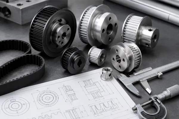
- Dimensioned drawingin STEP, IGES, DWG, DXF, SLDPRT or PDF. A 3D model alone is not enough, because tolerance classes and surface callouts live on the 2D drawing.
- Quantity, including whether this is a prototype run or production. Custom orders start from 20 pieces and scale to 10,000+ per run, and the quantity tier changes the manufacturing route, not just the unit price.
- Belt referencefrom Step 1.
- Application contextin one or two lines: torque, speed, duty cycle, environment. This is what allows a DFM review to catch problems your drawing did not encode.
Compared with the supplier category pages that dominate this search — which list customization options such as flanges, keyways and bushings without ever assembling them into a submittable sequence — the last item is the one that returns the most value. A drawing tells a supplier what to make. Application context tells them whether it will work.
Done when: one email contains all four, and you have not written “please advise” anywhere in it.
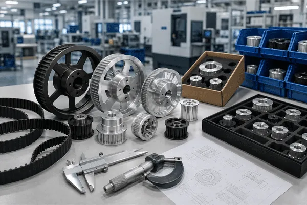
البكرات الزمنية المخصصة: كيفية تحديد مواصفاتها وتوريدها
What Happens to Your Package After You Send It
KTD’s route on custom pulleys runs: DFM review → prototype → First Article Inspection → mass production → CMM and material inspection → delivery with traceability. The company states that this operates under an ISO 9001:2015-certified quality management system; ISO identifies ISO 9001 as the internationally recognized quality management system standard, published by the International Organization for Standardization.
Two points inside that sequence are worth planning around. DFM feedback arrives before quotation, which means design changes are still cheap at that stage. First Article Inspection is where your tolerance classes get verified against the actual part, so an FAI report that arrives without the dimensions you care about most means those dimensions were not called out as critical on the drawing.
الأسئلة الشائعة
Q: What is the minimum quantity for a custom timing pulley?
A: Custom orders start from 20 pieces. Below that, the tooling and setup dominate the unit price to the point where the economics rarely make sense against modifying a stock pulley.
Q: Can you machine a custom bore into a standard pulley instead of making one from scratch?
A: Often yes, and it is the faster route when the profile, tooth count and face width are all standard and only the mounting interface is special. Send the stock part number alongside your bore requirement.
Q: H7 or H6 — how do I decide?
A: H7 is appropriate for general drives where a keyway carries torque and small clearance is acceptable. Specify H6 when the pulley sits on a servo or stepper shaft and the drive has a positioning repeatability specification, because bore clearance transfers to the load as lost motion.
Q: Which drawing format should I send?
A: STEP, IGES, DWG, DXF, SLDPRT and PDF are all accepted. Send a 3D model plus a 2D dimensioned drawing together. The model resolves geometry, the drawing carries tolerance classes, surface callouts and datums.
Q: Do I need to specify the tooth profile if I already gave the belt?
A: State it anyway. Belts of similar pitch from different profile families are not interchangeable on the same pulley, and a belt part number that a supplier has to look up is a question waiting to happen.
Q: How is pricing determined?
A: Pricing is project-specific and provided upon quotation based on material, dimensions, machining complexity, quantity, surface treatment and other technical requirements.
Q: Can flanges be added to a pulley after machining?
A: Bolted or pressed flanges can be added as separate components, which is common when a drive is modified in the field. On a new design, machining flanges integral to the pulley is more concentric and removes a fastener from the assembly.












 10:39
10:39